

Sieving Machine Integration Guide: Designing a Feeding System for Controlled Powder Intake and Screening
Post Date: 2026-08-17
Introduction
In modern powder-processing facilities, the screening stage needs to work together with upstream material handling. Before powder reaches a sieving machine, it must be introduced into the process in a suitable and manageable way. An appropriately designed Feeding system can serve as the interface between material storage and screening equipment, helping organize powder intake and establish a consistent process sequence.
Rather than treating the feeder and sieving machine as two independent pieces of equipment, an integrated design considers the material source, feeding point, screen inlet, production requirements, control strategy, cleaning access, and downstream collection together.
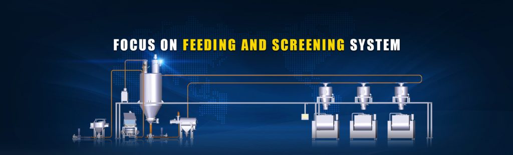
This guide discusses practical considerations for designing a Feeding system around a sieving machine while avoiding universal performance claims. Actual equipment selection should be based on the characteristics of the material and the operating conditions of each production line.
1. Define the Function of the Feeding System
The first step is to determine exactly what the Feeding system needs to do.
A basic powder-processing route may be:
Material Storage → Feeding System → Sieving Machine → Collection
Depending on the production line, the feeding stage may be responsible for:
- Receiving powder from upstream equipment
- Controlling material entry into the screening stage
- Connecting different equipment elevations
- Providing an enclosed transfer route where appropriate
- Supporting automated material supply
- Coordinating with upstream and downstream equipment
The Feeding system should be designed around these functions rather than selected solely according to a catalog model.
2. Establish the Powder Intake Point
The location where powder enters the Feeding system affects the overall equipment layout.
Possible intake sources include:
Storage Hopper
Storage Hopper → Feeding System → Sieving Machine
This is a common configuration for powders stored before screening.
Big Bag Feeding Station
Big Bag Feeding Station → Feeding System → Sieving Machine
This arrangement can connect bulk-bag unloading with downstream screening.
Mixer or Processing Equipment
Mixer → Feeding System → Sieving Machine
This may be considered when screening is required after mixing or another upstream process.
Vacuum Feeder
Vacuum Feeder → Feeding System / Screening Interface → Sieving Machine
This can be considered when pneumatic transfer forms part of the material-handling process.
The correct intake arrangement depends on the upstream equipment and material characteristics.
3. Understand the Screening Objective First
A Feeding system should ultimately support the requirements of the downstream sieving process.
Determine whether the sieving machine is intended to:
- Remove oversized particles
- Separate different particle-size fractions
- Screen powder before packaging
- Prepare material for another processing stage
- Remove selected agglomerates
Once the screening objective is established, the feeding arrangement can be designed around the required material entry conditions.
The overall relationship is:
Screening Objective → Sieving Machine → Feeding Requirements → Material Source
4. Analyze Powder Characteristics
Powder properties can influence how the Feeding system should be configured.
Bulk Density
Bulk density affects the amount of powder occupying a specific volume and should be considered when determining the feeding arrangement.
Flowability
Free-flowing and cohesive powders may require different intake and discharge designs.
Particle Size
Fine powders can behave differently from coarse particles during material transfer.
Moisture
Moisture can influence flow behavior and, for some materials, increase the possibility of agglomeration.
Abrasiveness
Abrasive materials may require appropriate consideration of contact components and maintenance.
Temperature
The temperature of the material and surrounding process should be considered when selecting equipment and materials of construction.
5. Design the Feeding Hopper or Intake Section
The intake section is an important part of controlled powder supply.
Depending on the material, the design may involve:
- Feed hopper
- Inlet connection
- Flow-control components
- Level monitoring
- Discharge outlet
- Agitation or auxiliary flow-assistance equipment where appropriate
The design should help the powder enter the downstream process under conditions suitable for the application.
For cohesive powders, particular attention may be required around the transition from storage to feeding.
6. Match the Feeding Outlet to the Sieving Machine
The interface between the Feeding system and sieving machine should be clearly defined.
Evaluate:
- Inlet dimensions
- Connection type
- Feeding direction
- Installation height
- Material-entry location
- Required material supply conditions
A typical arrangement is:
Feeding System → Sieving Machine Inlet
The physical connection should be confirmed before fabrication or installation.
This helps avoid problems caused by mismatched equipment dimensions or unsuitable transfer directions.
7. Select the Appropriate Sieving Machine
The feeding arrangement should be compatible with the selected screening technology.
Rotary Vibrating Sieve
A rotary vibrating sieve can be used for a range of powder screening and classification applications.
Feeding System → Rotary Vibrating Sieve
The appropriate mesh and configuration depend on the material and required separation.
Centrifugal Sifter
A centrifugal sifter can be considered for suitable continuous powder screening processes.
Ultrasonic Vibrating Screen
For certain fine-powder applications, an ultrasonic-assisted screen may be considered when compatible with the material and mesh requirements.
Linear Vibrating Screen
A linear vibrating screen may be appropriate for different bulk-material screening tasks.
The Feeding system should be selected after the actual screening requirements are understood.
8. Consider Controlled Powder Intake
Controlled intake is particularly important when the screening stage has defined material-processing requirements.
The design can consider:
Storage Capacity → Feed Control → Screening Capacity → Collection Capacity
Instead of simply transferring material as quickly as possible, the system should be evaluated according to the actual process capacity.
Important factors include:
- Required throughput
- Feeding rate
- Screening capacity
- Material characteristics
- Production schedule
- Collection capacity
Actual performance depends on the complete system and operating conditions.
9. Design for Batch Processing
A batch production line may use the Feeding system to introduce a defined quantity of material into the sieving machine.
A representative sequence is:
Batch Preparation → Material Intake → Controlled Feeding → Screening → Collection
The control system may use signals from material-level sensors or process equipment to determine when feeding begins or stops.
This approach can be considered where the production process is organized around defined batches.
10. Design for Continuous Processing
Continuous powder-processing lines require a different feeding strategy.
A possible workflow is:
Continuous Material Supply → Feeding System → Sieving Machine → Continuous Collection
The Feeding system and screening equipment should be evaluated together to determine whether the material supply conditions are suitable for continuous operation.
Where necessary, buffer hoppers, level monitoring, or automated control can be incorporated into the system.
11. Consider Feeding System Location
Plant layout has a direct effect on the Feeding system design.
Before installation, evaluate:
- Distance between storage and screen
- Equipment elevation
- Available floor space
- Access for operators
- Maintenance clearance
- Pipeline or chute routing
- Collection equipment location
A compact production area may require a different configuration from a large multi-level plant.
The layout should be finalized together with equipment connection points.
12. Consider Different Powder Sources
A flexible production facility may handle materials from several sources.
For example:
Flour Processing
Flour Hopper → Feeding System → Sieving Machine
Food Ingredient Processing
Ingredient Storage → Feeding System → Sieving Machine
Chemical Processing
Chemical Powder Storage → Feeding System → Sieving Machine
Bulk Bag Processing
Big Bag Station → Feeding System → Sieving Machine
The material source should be considered when selecting the intake design, connection dimensions, and feeding method.
13. Food Powder Applications
For food powders, the Feeding system should be designed with the complete hygienic process in mind.
Potential applications include:
- Flour
- Starch
- Powdered sugar
- Cocoa powder
- Protein powder
- Other dry ingredients
Important considerations include:
Material-Contact Components
Components contacting the product should be suitable for the intended application and applicable requirements.
Cleaning Access
The equipment should allow practical access to areas requiring inspection or cleaning.
Product Changeovers
Facilities processing multiple powders should establish appropriate cleaning and changeover procedures.
Residual Material
The system layout should consider locations where powder may remain after production.
14. Chemical and Industrial Powder Applications
Chemical and industrial powders can have different feeding requirements from food ingredients.
Evaluate:
- Chemical compatibility
- Flowability
- Bulk density
- Particle size
- Abrasiveness
- Moisture
- Temperature
- Special handling requirements
If combustible or hazardous powders are involved, the entire feeding and screening installation should be assessed according to applicable safety standards and regulations.
15. Consider Enclosed Feeding
For powder-processing applications where an enclosed transfer route is appropriate, the Feeding system can be incorporated into a closed material-handling arrangement.
A representative process is:
Storage → Enclosed Feeding → Sieving Machine → Collection
An enclosed arrangement can reduce the number of open manual transfer points.
However, actual dust-control performance depends on the complete installation, including equipment sealing, filters, connections, material properties, and operating conditions.
16. Integrate Level Monitoring
Level monitoring can help coordinate powder intake and screening operations.
Potential monitoring locations include:
- Material storage hopper
- Feeding hopper
- Receiving hopper
- Finished-material collection vessel
Signals from these points can be incorporated into the control system where appropriate.
For example:
Low Material Level → Feeding Request
or:
Receiving Vessel Full → Feeding Stop
The exact control logic depends on the production process and selected automation components.
17. Coordinate Feeding with Sieving Machine Status
A Feeding system can be incorporated into a coordinated equipment sequence.
One possible logic is:
Sieving Machine Ready
↓
Feeding System Enabled
↓
Powder Intake Begins
↓
Screening Continues
↓
Collection Level Monitored
If the downstream machine stops for inspection or maintenance, the feeding operation may also need to respond according to the control strategy.
Proper interlocking can help prevent unsuitable operating sequences.
18. Plan the Downstream Collection System
The screening stage should not be considered complete until screened material has been collected.
A complete arrangement may be:
Feeding System → Sieving Machine → Fine Material Collection → Further Processing
Where oversized material is separated:
Sieving Machine → Oversized Material Collection
Collection vessels, hoppers, bins, or downstream conveyors should be included in the original layout.
19. Design for Material Changeovers
If a single screening line processes several powders, the Feeding system should support an appropriate changeover procedure.
Consider:
- Cleaning requirements
- Residual powder
- Feed hopper cleaning
- Pipeline cleaning
- Screen replacement
- Collection equipment
- Product identification
For food applications, cleaning and sanitation procedures should follow the facility's applicable requirements.
20. Include Maintenance Access from the Beginning
Maintenance access should be part of the initial design rather than an afterthought.
Feeding System
Inspect:
- Feed hopper
- Valves
- Seals
- Sensors
- Discharge components
Sieving Machine
Inspect:
- Screen mesh
- Screen frame
- Inlet
- Discharge
- Operating components
Transfer Connections
Check:
- Sealing points
- Connections
- Material accumulation
- Physical condition
Maintenance schedules should follow equipment recommendations and actual operating conditions.
21. Practical Integration Example
Consider a flour-processing application where flour must be screened before packaging.
Step 1: Storage
Flour is stored in a hopper.
Step 2: Controlled Intake
The Feeding system receives flour from the hopper.
Step 3: Material Supply
The Feeding system transfers flour toward the screening equipment under the designed feeding conditions.
Step 4: Screening
A suitable sieving machine separates material according to the selected screen specification.
Step 5: Collection
The screened flour enters the collection system.
Step 6: Packaging
The accepted material proceeds to the packaging stage.
The simplified workflow is:
Flour Storage → Feeding System → Sieving Machine → Collection → Packaging
The actual equipment and control configuration should be determined according to the material, production capacity, and plant layout.
22. Gaofu Feeding System for Sieving Machine Integration
The Gaofu Feeding System can be considered for powder-processing applications where controlled material intake is required before screening.
Depending on the process, it can be integrated with:
- Rotary Vibrating Sieves
- Centrifugal Sifters
- Ultrasonic Vibrating Screens
- Linear Vibrating Screens
- Vacuum Feeders
- Big Bag Feeding Stations
- Other customized screening equipment
Configuration can be evaluated according to:
- Material properties
- Intake requirements
- Feeding rate
- Equipment layout
- Screening objectives
- Production mode
- Automation requirements
This allows the feeding stage to be planned as part of the complete screening workflow.
Why Choose Gaofu Machinery?
Gaofu Machinery provides equipment and system solutions for screening, feeding, conveying, and powder processing.
Its product range includes:
- Feeding Systems
- Vacuum Feeders
- Big Bag Feeding Stations
- Rotary Vibrating Sieves
- Centrifugal Sifters
- Filtration Sieves
- Linear Vibrating Screens
- Ultrasonic Vibrating Screens
Equipment selection should be based on actual material characteristics, process requirements, installation conditions, and applicable industry standards.
Conclusion
Designing a Feeding system for controlled powder intake requires a clear understanding of the entire screening process. The feeding stage must connect the material source with the sieving machine while considering powder characteristics, required supply rate, equipment interfaces, plant layout, collection, automation, cleaning, and maintenance.
A well-planned process can follow:
Material Source → Controlled Feeding → Sieving → Collection → Further Processing
The Gaofu Feeding System can be configured with different conveying and screening solutions according to application requirements. By evaluating material intake and screening as connected stages, powder-processing facilities can develop a more organized production layout suited to their specific operating conditions.