

Flour Sieve Integration Guide: Connecting a Feeding System with Screening Equipment for Controlled Material Flow
Post Date: 2026-09-11
In flour processing, the connection between a feeding system and screening equipment is an important part of production-line design. A flour sieve can provide the required screening function, but its operation also depends on how material enters the screening chamber. If the connection is poorly planned, problems such as uneven loading, material accumulation, excessive vibration transfer, or difficult maintenance may affect the overall process.
A well-planned connection should therefore be considered as more than simply attaching a feeding device to a flour sieve. The design should establish a suitable material path, coordinate equipment interfaces, provide appropriate access for inspection, and account for the characteristics of flour and other powder materials.
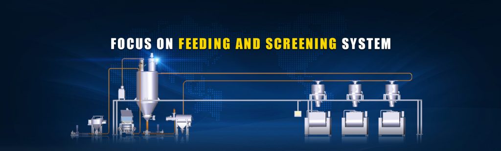
For flour mills, food manufacturers, and ingredient processors, a Feeding system can be configured around the requirements of the flour sieve to create a more organized material-handling process.
1. Start with the Material Path
Before selecting connection components, it is useful to map the complete material route:
Material Storage → Feeding System → Transition Connection → Flour Sieve → Qualified Material Collection
This simple process diagram helps engineers identify where material is stored, how it is released, how it reaches the screening equipment, and where screened material goes afterward.
The connection between the Feeding system and flour sieve should maintain a clear and practical material path. Unnecessary bends, sharp transitions, or poorly positioned outlets can make powder handling more complicated and may create areas where material accumulates.
For flour applications, the material path should also consider powder characteristics such as particle size, moisture content, flowability, bulk density, and the tendency of the material to adhere to surfaces.
The final configuration should be determined according to the actual flour characteristics and production requirements rather than relying on one standard connection arrangement.
2. Match the Feeding Outlet with the Flour Sieve Inlet
One of the first technical points to evaluate is the relationship between the Feeding system outlet and the flour sieve inlet.
The two pieces of equipment may have different dimensions, connection positions, and structural arrangements. A suitable transition section can bridge these differences while maintaining a practical route for material movement.
Important factors include:
- Inlet and outlet dimensions
- Connection height
- Centerline alignment
- Transition-section geometry
- Available installation space
- Cleaning and inspection access
- Material-contact surface requirements
- Equipment maintenance requirements
A properly planned transition can reduce unnecessary material accumulation and make the overall equipment arrangement easier to inspect.
For custom flour-processing lines, the connection dimensions should be confirmed during system engineering rather than determined only after the equipment has been installed.
3. Consider How the Feeding System Meets the Sieve
A flour sieve is a vibrating piece of screening equipment in many processing applications. Its movement means that the connection cannot simply be treated like a rigid structural joint.
The interface should be designed with the operating characteristics of both machines in mind.
Engineers may need to consider whether the connecting section should accommodate relative movement, how the connection is supported, and whether the arrangement could transmit unwanted mechanical forces between equipment.
Flexible connection components may be considered where appropriate. Their exact design depends on equipment structure, operating conditions, material characteristics, and applicable engineering requirements.
This distinction is important: the material connection should support powder transfer while the equipment structure should remain mechanically suitable for the operating environment.
4. Avoid Creating an Unnecessary Material Accumulation Zone
Flour is a fine powder, and poorly designed transitions can create areas where material remains after normal operation.
Potential accumulation areas may include:
- Dead corners
- Oversized transition chambers
- Abrupt changes in direction
- Poorly positioned inlet sections
- Internal ledges
- Unused branches or openings
A compact and appropriately shaped connection can make the material route easier to understand and inspect.
For food-processing applications, this consideration is also relevant to cleaning and product changeover. The connection should allow operators to identify potential residue areas and access the relevant components according to the plant's sanitation procedures.
The goal is not simply to make the connection shorter. It is to create a material path that is practical for operation, inspection, cleaning, and maintenance.
5. Coordinate the Feeding Point with the Screening Chamber
Where material enters the flour sieve can influence how the incoming material interacts with the screening surface.
If the feeding point is poorly positioned, the incoming flour may not be distributed across the available screening area as intended. Depending on the equipment configuration, this may reduce the effective use of the screen surface or create localized material loading.
The Feeding system should therefore be selected and positioned together with the flour sieve rather than treated as an independent piece of equipment.
During engineering, manufacturers and users can evaluate:
- The expected material entering the sieve
- The inlet position of the screening machine
- The required screening stages
- The screen specification
- The desired discharge arrangement
- Available installation space
This approach helps establish a connection that is compatible with the complete screening process.
6. Keep Inspection and Maintenance in the Design
A connection that works during initial installation may still be inconvenient if operators cannot inspect or maintain it easily.
For a flour sieve system, engineers should consider how operators will:
- Inspect the feeding connection
- Check for material residue
- Access seals and flexible connectors
- Remove components when necessary
- Inspect the screen
- Clean relevant contact surfaces
- Check connection integrity
Maintenance access should be considered during the layout stage.
For example, a transition connection positioned too close to another machine may make later maintenance more difficult. Similarly, components that require frequent inspection should not be hidden behind permanent structures without an appropriate access arrangement.
Good integration therefore considers the complete equipment lifecycle rather than installation alone.
7. Pay Attention to Dust Management
Fine flour particles can become airborne during material transfer, especially when powder enters or leaves equipment at unsuitable points.
A Feeding system and flour sieve can be arranged as part of a more enclosed material-handling route where appropriate. Seals, covers, connection points, and dust-collection arrangements should be evaluated according to the material and plant environment.
For facilities handling combustible flour dust, the complete system should also be assessed for applicable explosion-protection and workplace-safety requirements.
The Feeding system itself should not be considered a standalone solution for dust control. Dust management normally involves the complete material-handling system, including equipment enclosure, ventilation, collection, grounding, electrical design, and operating procedures.
8. Select the Feeding System According to the Flour Sieve
Different flour-processing lines may require different feeding arrangements.
For example, a production line handling material from bulk bags may use a Big Bag Feeding Station before conveying material toward the flour sieve. A vacuum conveying arrangement may be considered where enclosed powder transfer is required. Other production lines may use a hopper-based or customized Feeding system according to their process layout.
The key is to define the process requirements first.
A selection checklist can include:
| Evaluation Point | Questions to Consider |
|---|---|
| Material | What type of flour or powder is being processed? |
| Capacity | What material throughput is required? |
| Feeding method | How does material arrive at the production line? |
| Sieve | What screening equipment and inlet arrangement are used? |
| Connection | What dimensions and interfaces are required? |
| Hygiene | What cleaning and sanitation procedures apply? |
| Layout | What installation space is available? |
| Maintenance | Which components require regular access? |
| Safety | What dust and electrical safety requirements apply? |
This method helps avoid selecting a Feeding system based solely on nominal capacity or equipment appearance.
9. A Practical Integration Example
Consider a flour-processing line in which flour is supplied from a bulk material source and must pass through a screening stage before entering the next production process.
A possible arrangement is:
Bulk Flour Supply → Feeding System → Powder Transfer → Flour Sieve → Screened Flour Collection → Downstream Processing
In this configuration, the Feeding system provides the material supply function, while the flour sieve performs the screening operation.
The engineering focus should be placed on the interfaces between these stages. The transfer route should have suitable dimensions, the connection should accommodate the operating characteristics of the equipment, and inspection points should be positioned according to maintenance requirements.
If the flour characteristics or production capacity change, the Feeding system and screening equipment should be reevaluated as a combined process rather than modifying only one component.
10. How Gaofu Machinery Approaches Feeding and Screening Integration
Gaofu Machinery provides Feeding system solutions for powder-processing applications and can develop equipment configurations according to different material-handling and screening requirements.
For flour applications, the Feeding system can be considered together with screening equipment, conveying arrangements, bulk-bag discharge equipment, and other upstream or downstream components.
The engineering process can take into account factors such as:
- Material characteristics
- Required processing capacity
- Equipment dimensions
- Feeding and discharge positions
- Connection requirements
- Cleaning considerations
- Installation conditions
- Operation and maintenance requirements
This customized approach allows the material-handling route to be planned around the actual production process instead of applying the same configuration to every flour-processing application.
For food and powder manufacturers, the final equipment selection should be confirmed through technical communication, material testing where necessary, and evaluation of the specific production environment.
Conclusion
Connecting a Feeding system with a flour sieve involves more than matching two pieces of equipment. The connection determines how material moves between processing stages and should be considered in relation to inlet geometry, equipment movement, material accumulation, inspection access, dust management, cleaning, and overall plant layout.
A practical integration strategy begins with the material path, then evaluates the interfaces between the Feeding system and screening equipment. By considering these factors during the engineering stage, manufacturers can develop a more organized flour-processing line that aligns with their actual material and production requirements.
Gaofu Machinery supports customized Feeding system and screening solutions for different powder-processing applications, with equipment configurations developed according to specific process conditions and customer requirements.