

Integrating a Salt Crushing Machine into a Complete Salt Processing and Material Handling System
Post Date: 2026-10-07
A salt crushing machine rarely operates as an isolated piece of equipment. In a modern salt-processing facility, crushed material may need to move from raw-material storage through feeding, size reduction, screening, conveying, intermediate storage, and finally to packaging or another industrial process.
For this reason, integrating a Double Roller Crusher successfully involves more than determining whether the crusher can reduce salt to the required size. The connections between the crusher and the surrounding equipment can also influence material flow, operating stability, inspection access, cleaning, and process control.
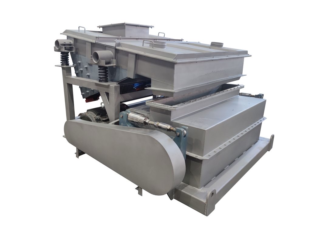
Gaofu Machinery's product portfolio covers crushing, screening, conveying, feeding, and system equipment, allowing these functions to be considered together when planning a salt-processing application.
This article examines how a Double Roller Crusher can be integrated into a complete salt processing and material handling system, with particular attention to equipment interfaces and coordinated operation.
1. Think of the Crusher as One Processing Node
A useful starting point is to treat the Double Roller Crusher as one node within the overall material-flow network.
A simplified system may look like:
Raw Salt Storage → Feeding → Double Roller Crusher → Screening → Conveying → Product Storage → Packaging
Depending on the application, some stages may be removed, repeated, or rearranged.
For example, a pre-screen can be installed before the crusher when only oversized material requires additional size reduction:
Raw Salt → Pre-Screening → Crusher → Re-Screening → Product
Alternatively, crushed salt may be transferred directly to another industrial process without a separate classification stage.
The correct configuration depends on the feed material, required product specification, production rate, and downstream process.
2. Define the Material-Flow Interfaces First
Before connecting individual machines, identify where material changes from one processing stage to another.
Typical interfaces include:
- Storage to feeder
- Feeder to crusher
- Crusher to conveyor
- Crusher to screen
- Screen to product conveyor
- Oversize discharge to reprocessing
- Product conveyor to storage
- Storage to packaging
At every interface, ask three basic questions:
- How does material enter the next machine?
- At what rate does it enter?
- What happens if the next machine temporarily stops?
These questions can reveal potential bottlenecks before equipment is installed.
3. Connecting the Feed System to the Double Roller Crusher
The crusher needs a suitable material supply arrangement.
A feed hopper, feeder, conveyor, or another upstream device may be used depending on the plant configuration.
The feeding system should be evaluated for:
- Feed rate
- Material distribution
- Hopper capacity
- Feed opening
- Material bridging
- Surge conditions
- Access for inspection
- Cleaning requirements
The purpose is to deliver material to the crusher in a condition consistent with its intended operating range.
Gaofu's salt-crusher information lists model-specific feed and discharge dimensions and capacity ranges, illustrating why the feeder and crusher should be considered as a matched pair rather than selected independently.
4. Avoid Treating Hopper Capacity as Crusher Capacity
A large feed hopper does not necessarily mean the crushing system can process material at a higher rate.
The actual flow may be limited by:
- Feeder capacity
- Crusher capacity
- Conveyor capacity
- Screen capacity
- Product-storage capacity
For example:
Hopper → Feeder → Crusher → Conveyor
If the feeder cannot provide the required flow, increasing the crusher size alone will not resolve the limitation.
Similarly, if the conveyor cannot remove crushed material quickly enough, the discharge side may become the limiting point.
System capacity should therefore be considered as a chain rather than a single equipment specification.
5. Use a Feeder to Regulate Material Delivery
A feeder can provide a controlled transition between bulk storage and crushing.
Depending on the application, the system may use:
- Vibratory feeding
- Screw feeding
- Belt feeding
- Other metering arrangements
The choice depends on the salt condition, required capacity, layout, and equipment configuration.
The important integration principle is that the feeder should deliver material in a way that matches the crusher's intended operating conditions.
Uncontrolled surges can make the material flow less predictable, while insufficient feeding may prevent the downstream system from operating at its intended production rate.
6. Design the Crusher Inlet as an Interface
The inlet of the Double Roller Crusher should be considered together with the upstream chute or feeder.
The transition should provide:
- Appropriate alignment
- Adequate opening
- Controlled material direction
- Access for inspection
- Protection against excessive accumulation
Where conveyors or elevators feed the crusher, the transfer point should be evaluated carefully.
A poorly positioned discharge can cause material to concentrate on one side of the crusher rather than distribute appropriately across the available working area.
7. Integrating the Crusher with a Conveyor
After crushing, material normally needs to leave the machine continuously or in controlled batches.
A conveyor may transfer material to:
- A screen
- A storage hopper
- A packaging system
- Another processing machine
- A reprocessing route
The conveyor should be evaluated according to the crusher's discharge characteristics and the requirements of the next stage.
Important considerations include:
- Conveyor capacity
- Transfer height
- Belt or conveying surface
- Material containment
- Cleaning access
- Inspection access
- Emergency stopping
- Layout space
The goal is to prevent the crusher from becoming isolated from the rest of the material-handling system.
8. Decide Whether Screening Belongs Before or After Crushing
Screening can occupy different positions depending on the process objective.
Screening Before Crushing
Salt Feed → Screen → Oversize → Double Roller Crusher
This arrangement can be considered when a significant portion of the incoming salt already meets the required size.
The acceptable fraction can bypass the crusher while only the oversize fraction receives additional size reduction.
Screening After Crushing
Salt Feed → Double Roller Crusher → Screen → Product Fractions
This arrangement can be useful when the crusher first reduces the material and the screen subsequently separates it into defined fractions.
Screening Before and After Crushing
Feed → Pre-Screen → Crusher → Final Screen
This approach can be considered when both selective crushing and final classification are required.
The appropriate arrangement depends on the actual material-size distribution and product requirements.
9. Connect the Crusher and Screen as Complementary Equipment
The Double Roller Crusher and screening machine perform different functions.
The crusher reduces material size.
The screen classifies material.
A well-coordinated system may therefore use:
Crusher → Screen → Target Product + Oversize + Other Fractions
Gaofu's product range includes multiple screening and conveying technologies alongside its salt crusher, making it possible to consider the crushing and classification stages as connected process functions.
The screen should be selected according to the material, required fractions, capacity, and downstream requirements rather than simply matching the crusher model.
10. Plan the Oversize Route
If screening follows crushing, an oversize fraction may remain.
The plant should define what happens to this material.
Possible routes include:
Oversize → Return Conveyor → Double Roller Crusher
or:
Oversize → Separate Collection → Further Processing
or:
Oversize → Reject Route
The correct route depends on product specifications and process economics.
A return loop can be useful when the oversized material is suitable for reprocessing, but the additional conveying and crushing load must also be considered.
11. Design the Reprocessing Loop Carefully
A crusher-screen loop can become a separate material-flow circuit:
Crusher → Screen → Oversize → Return → Crusher
Before implementing such a loop, the designer should consider:
- Expected oversize percentage
- Return-conveyor capacity
- Additional crusher load
- Storage requirements
- Control logic
- Potential accumulation
- Product quality
- Access for cleaning and inspection
The return stream should be treated as part of the system capacity calculation.
For example, a crusher processing a certain fresh-feed rate may experience a higher total internal material flow if a substantial portion of the discharge is continuously recycled.
12. Integrate Product Storage After Crushing
A product-storage hopper or silo can separate the crushing stage from downstream packaging or processing.
For example:
Crusher → Screening → Product Conveyor → Product Hopper → Packaging
The storage volume can provide a buffer when upstream and downstream equipment operate at different rates.
It may also support:
- Batch production
- Packaging changes
- Temporary downstream stoppages
- Product segregation
- Production scheduling
The storage system should be designed around the actual material properties and production requirements.
13. Separate Different Salt Product Grades
Some salt-processing facilities produce more than one particle-size grade.
After crushing and screening, separate outlets can direct different fractions to different destinations.
For example:
Screen
→ Fine Fraction → Product A
→ Target Fraction → Product B
→ Oversize → Reprocessing
This arrangement can reduce the need to mix differently sized products after classification.
It also makes the material-flow route easier to document.
Each outlet should be clearly identified and connected to the appropriate storage or processing destination.
14. Coordinate the Crusher with Packaging Equipment
For salt destined for packaging, the crusher is several process stages away from the final packaging machine.
A possible route is:
Raw Salt → Crusher → Screen → Product Storage → Weighing → Packaging
The crusher therefore needs to be coordinated indirectly with the packaging rate.
If packaging demand changes, product storage may absorb some of the difference. Without sufficient buffering, a stoppage at the packaging stage could eventually affect upstream crushing.
The material-handling system should therefore account for both upstream production and downstream consumption.
15. Consider Vertical Material Transfer
Not every plant can be arranged entirely on one floor.
Vertical conveying may be needed between:
- Ground-level raw-material storage
- Crusher platform
- Screening floor
- Product silo
- Packaging area
Gaofu offers vertical hoisting equipment for material lifting and describes configurations for different process requirements.
When integrating vertical transfer with a Double Roller Crusher, consider:
- Elevator capacity
- Feed/discharge alignment
- Intermediate storage
- Maintenance access
- Material containment
- Cleaning
- Building height
The objective is to create a continuous material route without introducing unnecessary transfer points.
16. Reduce Unnecessary Transfer Points
Every transfer point can create another location requiring:
- Structural support
- Chutes
- Inspection
- Cleaning
- Sealing
- Maintenance
A shorter material route can therefore simplify system management.
However, minimizing transfer points should not come at the expense of necessary screening, storage, or inspection functions.
The appropriate design balances:
Short Material Route + Adequate Buffering + Safe Access + Process Flexibility
17. Consider Dust and Material Containment
Salt handling can generate airborne particles under certain operating conditions, particularly when material falls from height or when crushing creates fine material.
The system should therefore consider containment around:
- Crusher inlet
- Crusher discharge
- Transfer chutes
- Conveyor transitions
- Screening equipment
- Storage hoppers
- Packaging connections
Gaofu identifies dust-control and negative-pressure conveying among its material-handling and feeding system capabilities.
The actual dust-control arrangement should be designed according to the material, process, local regulations, and site-specific risk assessment.
For combustible or potentially hazardous dusts, the complete installation should additionally be assessed against applicable local safety requirements.
18. Think About Cleaning Across the Entire System
Cleaning cannot stop at the crusher.
If the Double Roller Crusher is cleaned but salt remains in:
- Feed chutes
- Conveyors
- Screening chambers
- Hoppers
- Transfer points
the overall cleaning process may still be incomplete.
This is particularly important for edible-salt applications or facilities that handle multiple products.
The integration design should therefore identify cleaning access throughout the material path.
19. Design for Inspection Access
Equipment integration should leave sufficient space around critical areas.
Inspection points may include:
- Crusher rollers
- Crusher gap mechanism
- Feed chute
- Discharge chute
- Conveyor transfer points
- Screen surface
- Bearings
- Drive systems
- Storage-hopper outlets
A system that is easy to operate but difficult to inspect can create avoidable maintenance challenges.
The layout should allow operators and maintenance personnel to reach relevant components without unnecessarily dismantling adjacent equipment.
20. Coordinate Equipment Controls
A complete material-handling system should also consider how individual machines respond to one another.
For example, if the downstream conveyor stops, the crusher should not necessarily continue receiving material indefinitely.
Similarly, if the screen stops, upstream material flow may need to be reduced or stopped.
A simplified control relationship could be:
Downstream Available → Crusher Permitted to Feed
Downstream Stop → Upstream Feed Reduced or Stopped
Storage Level Low → Material Supply Continues
Storage Level High → Upstream Supply Adjusted
The exact control sequence depends on the equipment and plant automation system.
The important principle is that the crusher should operate as part of a coordinated process rather than independently.
21. Use Interlocks Between Equipment Stages
Interlocks can help coordinate equipment start-up and shutdown sequences.
For example, a system may be designed so that:
- Downstream equipment starts first.
- Conveying equipment becomes available.
- Screening equipment starts.
- The Double Roller Crusher starts.
- The feeding equipment begins supplying material.
During shutdown, the sequence can be reversed so that upstream material supply stops before downstream equipment is stopped.
The actual control logic should be designed and validated by qualified engineering personnel according to the equipment and site safety requirements.
22. Consider Emergency Stop Locations
Material-handling systems contain multiple moving components.
Emergency stopping arrangements should therefore be considered across the integrated line rather than only at the crusher.
Potential areas include:
- Feed system
- Crusher
- Conveyors
- Screens
- Elevators
- Packaging interface
Emergency-stop design should comply with the applicable machinery-safety requirements for the installation.
The system should also define what happens to material remaining inside the equipment after an emergency stop.
23. Connect the Crusher to a Process Data System
Modern processing lines may benefit from recording operating information from several machines.
Depending on the automation level, useful data can include:
- Crusher running status
- Feed rate
- Motor condition
- Screen status
- Conveyor status
- Hopper level
- Product batch
- Production quantity
- Alarm status
The objective is not necessarily to collect every possible parameter.
Instead, the system should identify the data that helps operators understand material flow and respond to process changes.
24. Build the Material-Handling System Around Bottlenecks
A complete system should be evaluated by its limiting stage.
For example:
Feeder: 8 t/h
Crusher: 10 t/h
Screen: 7 t/h
Conveyor: 10 t/h
The screen becomes a potential capacity constraint even though the crusher has a higher nominal capacity.
Likewise, a large crusher cannot compensate for an undersized feeder.
This is why system integration requires coordinated capacity calculations.
Gaofu's published salt-crusher specifications include different model capacities, ranging from approximately 3–5 t/h to 20–40 t/h depending on model. These are manufacturer-published reference specifications for the listed configurations, not universal performance guarantees.
25. Consider Expansion During the Initial Integration
A plant may initially require one product grade but later add additional grades or higher production capacity.
Where practical, the initial layout can reserve space for:
- Additional screening equipment
- Larger storage
- Additional conveyors
- Product-diverting equipment
- Additional packaging routes
- Alternative material feeds
Future expansion should not be assumed to be necessary, but considering it during the initial design can help avoid unnecessary reconstruction later.
26. Example of an Integrated Salt Crushing Route
Consider a facility receiving bulk salt and preparing a controlled granular product.
A possible system is:
Bulk Salt Storage
↓
Feed Hopper
↓
Controlled Feeder
↓
Pre-Screen
↓
Oversize Fraction
↓
Double Roller Crusher
↓
Discharge Conveyor
↓
Final Screening
↓
Target Product
↓
Product Storage
↓
Packaging
The oversize fraction from the final screen may be directed back to the crusher if the product specification and material-handling capacity make reprocessing appropriate.
This arrangement separates the major functions:
- Storage manages inventory.
- Feeding regulates material supply.
- Screening separates fractions.
- The Double Roller Crusher performs size reduction.
- Conveyors transfer material.
- Product storage buffers production.
- Packaging prepares the final product.
The exact configuration should be adapted to the customer's material and process.
27. Example for Industrial Salt
An industrial salt line may use a different arrangement:
Raw Salt Storage
↓
Feeder
↓
Double Roller Crusher
↓
Conveyor
↓
Screening
↓
Industrial Product Storage
↓
Downstream Process
Here, packaging may not be required at all.
The crushed salt may instead be fed directly into another industrial process.
This illustrates why system integration should begin with the final destination of the material rather than using a fixed equipment sequence for every salt-processing application.
28. Food-Processing Integration Requires Additional Considerations
For edible salt, the complete system should be evaluated from a hygiene perspective.
This can include:
- Product-contact materials
- Cleaning access
- Product segregation
- Changeover procedures
- Foreign-material control
- Sealing
- Lubrication protection
- Applicable food-contact requirements
These requirements depend on the destination market and intended use.
A food-processing line should therefore be reviewed against the applicable regulations and the customer's internal food-safety procedures rather than relying on a generic “food grade” label.
29. Match the Crusher with Existing Equipment
Not every customer is building a new salt-processing line.
Some may already have:
- Conveyors
- Screens
- Feed hoppers
- Elevators
- Storage bins
- Packaging machines
In these cases, the Double Roller Crusher needs to be integrated into an existing system.
Useful information for the supplier can include:
- Existing equipment dimensions
- Current material flow
- Existing capacities
- Inlet and outlet elevations
- Conveyor directions
- Available installation space
- Electrical conditions
- Product requirements
This allows the new crusher to be evaluated as an addition to an existing material-handling network.
30. Site Layout Should Be Verified Before Manufacturing
Equipment drawings alone may not reveal every site limitation.
Before installation, the project team should verify:
- Floor dimensions
- Equipment elevations
- Access routes
- Structural loading
- Maintenance clearance
- Electrical connections
- Conveyor paths
- Discharge heights
- Cleaning routes
This can reduce the risk of discovering installation conflicts after equipment has already been manufactured.
Gaofu describes a service process that includes collecting application information, determining product data, designing a product plan, installation and debugging, and customer acceptance.
31. Commission the System in Stages
When the complete line is installed, commissioning can be approached systematically.
A possible sequence is:
Stage 1: Mechanical Inspection
Check equipment installation, fasteners, guards, chutes, conveyors, and connections.
Stage 2: Individual Equipment Testing
Test the feeder, crusher, screen, conveyors, and storage equipment according to their respective procedures.
Stage 3: Empty-Run Testing
Where applicable, confirm the operating direction, control logic, interlocks, and emergency stops without processing material.
Stage 4: Material Testing
Introduce salt gradually and observe material flow.
Stage 5: Process Verification
Check feed rate, discharge, screening, conveying, and product collection.
Stage 6: Production Adjustment
Adjust operating parameters according to the actual process results and equipment instructions.
The exact commissioning procedure should follow the manufacturer's documentation and applicable site-safety requirements.
32. Why System Integration Can Improve Process Coordination
Integrating the Double Roller Crusher with feeding, screening, and conveying equipment allows the crushing stage to be evaluated in the context of the complete material route.
Potential benefits of coordinated design include:
- More clearly defined material flow
- Better matching of equipment capacities
- Easier monitoring of bottlenecks
- More organized product routing
- Improved access planning
- More consistent process control
- Easier future modification
These are system-design objectives rather than guaranteed performance outcomes. Actual results depend on the material, equipment configuration, operating conditions, and engineering of the installation.
33. Gaofu Machinery: From Crusher to Material-Handling System
Gaofu Machinery's product range includes salt crushing equipment alongside screening, conveying, feeding, and automated material-handling systems.
Its published salt crusher uses a two-roller structure and provides adjustable crushing clearance. The company lists several configurations with different roller lengths and capacities for salt-processing applications.
For a complete salt-processing project, Gaofu can evaluate the relationship between the crushing stage and related equipment based on:
- Salt material
- Feed size
- Required output
- Production capacity
- Screening requirements
- Conveying distance
- Storage requirements
- Packaging or downstream process
- Site conditions
This system-oriented approach can help customers consider the Double Roller Crusher as part of the complete material-flow solution.
Conclusion
Integrating a Double Roller Crusher into a salt-processing facility requires more than connecting a feed hopper to a crusher and installing a conveyor at the outlet.
The crusher needs to work in coordination with:
Feeding → Crushing → Screening → Conveying → Storage → Packaging or Downstream Processing
Each interface can influence the next stage. Feeder capacity affects crusher supply. Crusher discharge affects conveying. Screening determines product routing. Storage can buffer production. Control logic coordinates equipment operation. Cleaning and inspection requirements influence physical layout.
For new installations, these relationships should be considered during the initial process design. For existing facilities, the same principles can help determine how a Double Roller Crusher can be added without creating unnecessary material-flow constraints.
By treating crushing, screening, feeding, conveying, storage, and controls as connected parts of one material-handling system, salt processors can develop a more coordinated equipment configuration based on their actual production requirements.
Gaofu Machinery can evaluate salt-processing projects according to the material, feed and discharge requirements, capacity, existing equipment, and downstream process, helping customers develop a Double Roller Crusher integration approach suited to the specific application.